
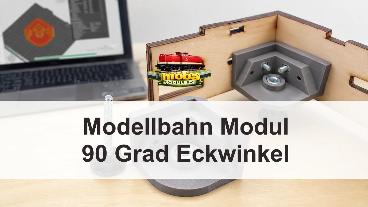

Inhaltsverzeichnis
- Warum rechtwinklige Ecken beim Modulbau wichtig sind
- Wie die Idee für den gedruckten Eckwinkel entstand
- Aufbau des 90-Grad-Eckwinkels
- Die integrierten Mutteraufnahmen
- M8-Stellfuß für die Höhenausrichtung
- Warum der Winkel im 3D-Druck entsteht
- Ein Winkel oder vier Winkel gleichzeitig drucken
- Verwendetes Material und Druckeinstellungen
- Was der Eckwinkel leisten kann
- Grenzen des gedruckten Bauteils
- Projektdateien zum Herunterladen
- Zum Schluss
- Technische Quellen und Hinweise
Ein rechteckiger Modulkasten wirkt zunächst einfach. Erst beim Zusammensetzen zeigt sich, ob die Seiten wirklich im rechten Winkel stehen und ob die gegenüberliegenden Diagonalen übereinstimmen. Aus diesem praktischen Problem entstand mein Eckwinkel für das Modellbahnmodul aus dem 3D-Druck. Ich wollte eine kompakte Werkstattlösung, die eine sauber ausgerichtete Ecke während der Montage unterstützt, die Verbindung der beiden Holzwände verstärkt und zugleich eine M8-Mutter für einen höhenverstellbaren Stellfuß aufnimmt.
Der Winkel ist kein Verkaufsprodukt und keine berechnete Industriekonstruktion. Er ist eine eigene, reproduzierbare und anpassbare Lösung für den Modulbau bei MOBA-Module. Die mittlere M8-Mutter hat dabei nur eine Aufgabe. Sie stellt das Gewinde bereit, in das ein M8-Stellfuß eingeschraubt werden kann.
Als praktische Ergänzung passen die vorhandenen Beiträge über den Modulkasten in Spur N für Segmente und Dioramen, den Modulbausatz Spur N für die Modelleisenbahn.
Warum rechtwinklige Ecken beim Modulbau wichtig sind
Zwei Bretter bilden nicht automatisch eine exakt rechtwinklige Ecke. Schon eine kleine Abweichung an einer Stirnseite kann sich über die Länge des Modulkastens fortsetzen. Dann stehen gegenüberliegende Seiten versetzt, Anschlussflächen liegen nicht sauber an und die gesamte Geometrie wird unnötig schwer kontrollierbar. Modulnormen von MOROP und FREMO befassen sich vor allem mit kompatiblen Schnittstellen, Profilen und mechanischen Verbindungen. Für die eigene Werkstatt bleibt trotzdem die grundlegende Aufgabe, den Kasten maßhaltig und verwindungsarm aufzubauen.
Ein zuverlässiger Anschlagwinkel kontrolliert die einzelne Ecke. Die Diagonalmessung kontrolliert dagegen den gesamten rechteckigen Kasten. Bei einem korrekt ausgerichteten Rechteck sind die beiden gegenüberliegenden Diagonalen gleich lang. Das ist keine Ersatzmessung für den Anschlagwinkel, sondern eine zweite Kontrolle auf einer größeren Länge. Erst wenn die Bretter auf einer ebenen Unterlage sauber ausgerichtet sind, wird der gedruckte Winkel eingesetzt und gleichmäßig befestigt.
Der Eckwinkel zieht schief zugeschnittene Bretter nicht automatisch gerade. Ein sauberer Aufbau benötigt weiterhin maßhaltige Holzteile, gerade Schnittkanten, eine ebene Arbeitsfläche, eine geeignete Holzverbindung und eine gleichmäßige Verschraubung. Bei größeren Modulen können außerdem Querstreben oder andere konstruktive Maßnahmen notwendig sein.
Wie die Idee für den gedruckten Eckwinkel entstand
Ich wollte für meine Modulkästen einen Winkel, der beim Ausrichten nicht nur punktuell anliegt. Zwei breite Anlageflächen sollten an den Holzwänden sitzen. Außerdem sollten die Befestigungsmuttern direkt im Druckteil Platz finden, damit die Schrauben nicht in ein gedrucktes Kunststoffgewinde schneiden. Die zusätzliche M8-Aufnahme entstand aus dem Wunsch, an derselben Ecke bei Bedarf einen Stellfuß einschrauben zu können.
Der 3D-Druck war dafür naheliegend, weil sich die Form im Modell an den vorhandenen Bauraum anpassen lässt. Die bereitgestellte Videoaufnahme zeigt eine umlaufende Modellansicht und bestätigt die kompakte Eckform, die abgestuften Innenbereiche, die seitlichen Bohrungen und die mittige Muttertasche. Das Video ist eine Modellvorschau und keine vollständige Montageanleitung.
Aufbau des 90-Grad-Eckwinkels
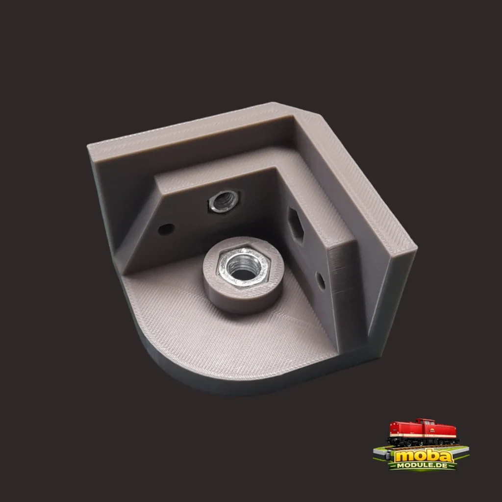
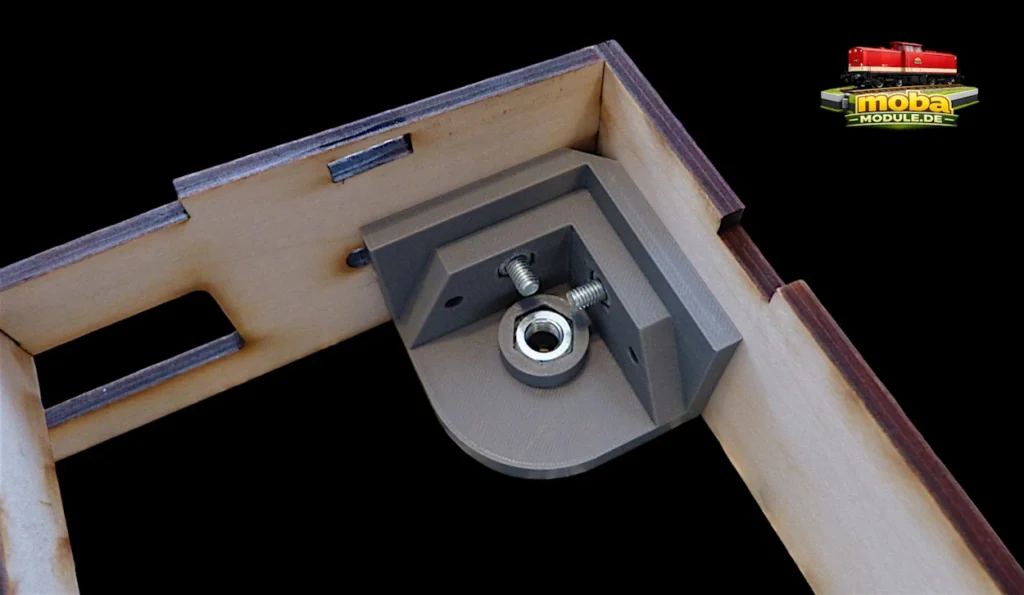
Das bereitgestellte Modell besitzt zwei rechtwinklig angeordnete Anlageflächen. Sie treffen in der Innenecke zusammen und werden durch abgestufte Bereiche verstärkt. Die Bodenfläche ist an der freien Außenseite abgerundet. In dieser Fläche sitzt die Aufnahme für die mittlere M8-Mutter. Seitliche Bohrungen führen zu den kleineren Muttertaschen in den beiden Wandbereichen.
Die Konstruktion ist damit auf eine Innenecke des Modulkastens zugeschnitten. Sie kombiniert die Ausrichtung an zwei Holzwänden mit einer kompakten Grundfläche.
Die integrierten Mutteraufnahmen
Seitliche Muttern für die Befestigung
An jeder der beiden Anlageflächen befindet sich ein Loch mit zugehöriger Mutteraufnahme. Die kleineren Muttern sitzen in diesen Taschen und ermöglichen die Verschraubung des Winkels mit den Holzwänden. Dadurch wird beim Anziehen nicht direkt ein Gewinde in den Kunststoff geschnitten. Die beiden kleineren Muttern für die Seitenteile sind für eine Schraube und Mutter M5.
M8-Mutter für den Stellfuß
Die mittlere M8-Mutter sitzt in einer Aufnahme der Bodenfläche. Sie dient ausschließlich als Gewinde für einen M8-Stellfuß. Der Gewindebolzen wird entsprechend der Einbaulage von unten in die Mutter eingeschraubt.
M8-Stellfuß für die Höhenausrichtung
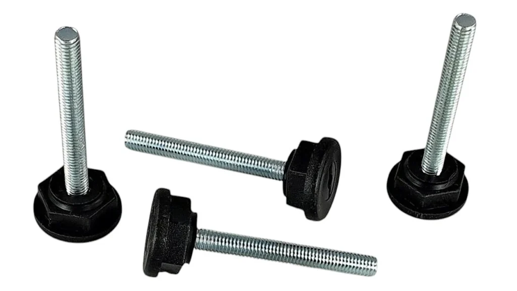
Der höhenverstellbare Stellfuß besitzt eine M8-Gewindestange. Diese Gewindestange wird in die im Winkel eingesetzte M8-Mutter eingeschraubt. Durch Ein- oder Ausschrauben lässt sich die Höhe der betreffenden Modulecke verändern. Mehrere Stellfüße können helfen, ein Modul auf einem unebenen Boden auszurichten. Auch FREMO beschreibt für Modulbeine eine Höhenverstellung zum Ausgleich von Bodenunebenheiten.
Warum der Winkel im 3D-Druck entsteht
Beim 3D-Druck können Muttertaschen, Bohrungen und Anlageflächen direkt in einem Bauteil kombiniert werden. Die Form lässt sich an einen bestimmten Modulkasten anpassen und später im 3D-Modell ändern. Einzelteile können reproduzierbar nachgedruckt werden. Für diese Form ist außerdem keine Metallbearbeitung erforderlich.
Das macht den gedruckten Winkel nicht pauschal besser als einen Metallwinkel oder eine klassische Holzverbindung. Ein Metallwinkel ist leicht erhältlich und mechanisch bewährt. Der gedruckte Eckverbinder bietet dagegen eine speziell angepasste Geometrie mit integrierten Mutteraufnahmen und der Option für den M8-Stellfuß. Welche Lösung sinnvoll ist, hängt vom Modulkasten, den vorhandenen Werkzeugen und der praktischen Erprobung ab.
Bei funktionalen FDM-Bauteilen beeinflusst die Orientierung auf dem Druckbett die Richtung der Schichten und damit das Verhalten unter Belastung. Auch die Zahl der Außenwände, die Drucktemperatur, der Materialfluss und die Layerhaftung wirken sich aus. Die Drucker-Dokumentation weist darauf hin, dass FDM-Teile richtungsabhängig belastbar sind und die Anzahl der Perimeter einen großen Einfluss auf die Festigkeit hat. Deshalb sollte ein angepasstes Modell neu bewertet und nicht nur geometrisch skaliert werden.
Ein Winkel oder vier Winkel gleichzeitig drucken
Für einen ersten Test ist ein einzelner Winkel sinnvoll. So lassen sich die Passung der M8-Mutter, die beiden seitlichen Muttertaschen und die Bohrungen kontrollieren, bevor ein kompletter Satz gedruckt wird. Ein fehlgeschlagener Test verursacht außerdem weniger Materialverlust. Ein einzelnes Ersatzteil kann später gezielt nachgedruckt werden.
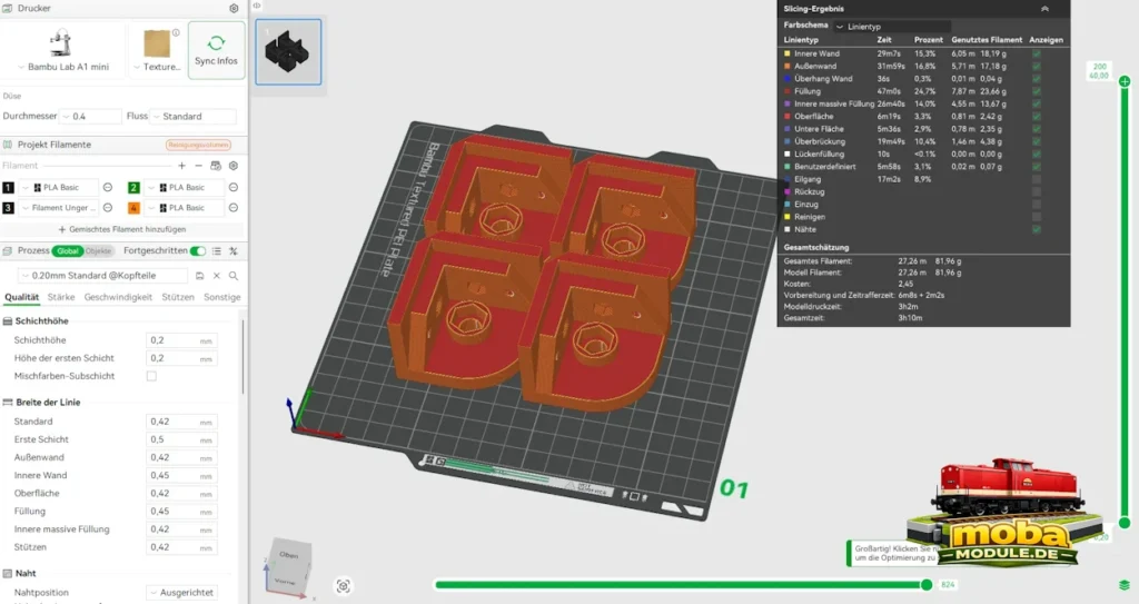
Die bereitgestellte Sliceransicht zeigt vier identische Winkel gemeinsam auf einer Druckplatte. Das entspricht einem Satz für die vier Ecken eines rechteckigen Modulkastens. Der gemeinsame Druck nutzt den Bauraum und läuft in einem Arbeitsgang. Dafür dauert er länger und ein Fehler kann mehrere Teile betreffen. Ich würde deshalb zuerst die Passung mit einem Einzelwinkel prüfen und erst danach den Vierersatz starten.
Verwendetes Material und Druckeinstellungen
Die zugängliche Sliceransicht zeigt für den Vierersatz ein Druckerprofil für den Bambu Lab A1 mini, eine Düse mit 0,4 Millimetern und eine Schichthöhe von 0,20 Millimetern. Die Vorschau errechnet für vier Winkel insgesamt 27,26 Meter Filament, 81,96 Gramm Material und eine geschätzte Gesamtdruckzeit von 3 Stunden und 10 Minuten. Diese Werte gehören ausschließlich zu dem sichtbaren Slicerprofil. Druckzeit und Materialverbrauch können je nach Drucker, Filament, Slicer-Version, Geschwindigkeit und Profil abweichen.
| Geprüfter Wert | Angabe der bereitgestellten Sliceransicht |
|---|---|
| Druckerprofil | Bambu Lab A1 mini |
| Düsengröße | 0,4 Millimeter |
| Schichthöhe | 0,20 Millimeter |
| Anordnung | Vier Winkel auf einer Druckplatte |
| Filament für den Vierersatz | 27,26 Meter und 81,96 Gramm |
| Geschätzte Gesamtdruckzeit | 3 Stunden und 10 Minuten |
Die Winkel bestehen aus PETG. Vor jedem Druck muss das Materialprofil bewusst geprüft und an das tatsächlich eingelegte Filament angepasst werden.
PETG bleibt für ein funktionales Werkstattteil eine nachvollziehbare Materialoption. Herstellerinformationen beschreiben PETG als zäh, temperaturbeständiger als gewöhnliches PLA und geeignet für technische Teile. Das Material kann bei ungünstigen Einstellungen Fäden ziehen. Außerdem hängen Maßhaltigkeit und Passung der Muttertaschen vom Drucker, vom Materialfluss und von der Kalibrierung ab. Bohrungen und Taschen können deshalb nach dem Druck leicht vom Modellmaß abweichen.
Eine normale 3MF-Projektdatei kann im Slicer von Bambu Lab geöffnet, kontrolliert und an Drucker, Material und eigene Einstellungen angepasst werden. Eine G-Code-3MF-Datei enthält bereits geslicte, maschinenspezifische Bewegungen und Einstellungen. Fremder G-Code darf nicht ungeprüft gestartet werden. Druckermodell, Düsengröße, Material, Bauraum und Profil müssen zur Datei passen.
Was der Eckwinkel leisten kann
Der Eckwinkel Modellbahnmodul 3D-Druck erleichtert einen wiederholbaren Montageablauf. Seine beiden Anlageflächen stützen die rechtwinklige Position der Holzwände. Die seitlichen Mutteraufnahmen ermöglichen eine definierte Verschraubung, und die mittlere M8-Mutter bietet das Gewinde für einen Stellfuß. Ein kompletter Vierersatz kann vier gleiche Ecken eines rechteckigen Kastens ausstatten.
- Er unterstützt den Aufbau einer sauber ausgerichteten 90-Grad-Ecke.
- Er verstärkt die montierte Verbindung der beiden Holzwände.
- Er integriert zwei seitliche Mutteraufnahmen für die Befestigung.
- Er ermöglicht das Einschrauben eines M8-Stellfußes.
- Er lässt sich im 3D-Modell an andere Holzdicken und Schraubenpositionen anpassen.
Diese Aussagen beschreiben die praktische Funktion der Konstruktion. Sie sind kein Belastungsnachweis.
Grenzen des gedruckten Bauteils
Der gedruckte Winkel ersetzt keine genaue Holzbearbeitung. Er ersetzt weder die Kontrolle des rechten Winkels noch die Diagonalmessung. Auch eine geeignete Verbindung der Holzteile, ausreichende Holzstärke, mögliche Querstreben, saubere Montage und praktische Erprobung bleiben notwendig.
FDM-Druckteile sind schichtweise aufgebaut. Ihre Eigenschaften hängen von Material, Orientierung, Wandzahl, Temperatur, Layerhaftung und Belastungsrichtung ab. Ein sichtbarer Druckfehler, eine schlecht sitzende Mutter oder ein beschädigtes Gewinde ist ein Grund, das Teil nicht einzubauen. Für diese Eigenentwicklung liegen keine geprüften Lastwerte und keine maximale Belastbarkeit vor.
Auch die Höhenausrichtung hat Grenzen. Ein weit herausgedrehter Stellfuß kann ungünstiger geführt sein als ein kurz eingestellter. Der konkrete Aufbau muss so gestaltet sein, dass das Modul sicher steht und bei größeren Abmessungen nicht allein auf kleinen Eckbauteilen oder einzelnen senkrechten Beinen vertraut.
Projektdateien zum Herunterladen
- Eckwinkel Module 90 Grad als 3MF
- Vier Eckwinkel Module 90 Grad als 3MF
- Eckwinkel STL-Datei
Die bereitgestellten Dateien dürfen für den privaten Nachbau und für eigene Anpassungen verwendet werden. Vorbereitete G-Code-Dateien müssen vor dem Druck auf Kompatibilität mit dem verwendeten Drucker, der Düse, dem Material und dem Druckprofil geprüft werden. Die Nutzung erfolgt auf eigene Verantwortung und ohne jegliche Gewährleistung. Eine kommerzielle Weitergabe oder ein Verkauf der Dateien ist ohne ausdrückliche Zustimmung nicht gestattet.
Zum Schluss
Der selbst konstruierte 90-Grad-Eckwinkel ist für mich eine praktische Ergänzung beim Modellbahnmodul bauen. Er hilft, eine zuvor sauber ausgerichtete Ecke zu halten, verstärkt die Verbindung der beiden Holzwände und nimmt die Befestigungsmuttern direkt im Druckteil auf. Die mittlere M8-Mutter stellt das Gewinde für einen höhenverstellbaren Stellfuß bereit.
Der größte Vorteil des 3D-Drucks liegt in der Anpassbarkeit. Maße, Muttertaschen und Bohrpositionen können im Modell verändert werden. Der größte Vorbehalt liegt ebenfalls im Herstellungsprozess. Passung, Materialprofil, Druckrichtung und Layerhaftung müssen für jedes reale Drucksystem kontrolliert werden. Ein Testdruck mit einem Winkel ist deshalb der vernünftige erste Schritt, bevor vier Teile gemeinsam gedruckt und in einen Modulkasten eingebaut werden.
Technische Quellen und Hinweise
Die folgenden Quellen wurden für die allgemeinen Hinweise zu Modulbau, verstellbaren Modulbeinen, PETG, FDM-Konstruktion, Wandlinien und 3MF-Projekten verwendet.
- MOROP. NEM Normen und NEM 900 Anlagen-Module. Abruf am 6. August 2026.
- FREMO. N-RE Modulkasten. Abruf am 6. August 2026.
- FREMO. N-RE Modulbeine. Abruf am 6. August 2026.
- Prusa Research. PETG Materialleitfaden. Abruf am 6. August 2026.
- Prusa Research. Modellierung mit Blick auf 3D-Druck. Abruf am 6. August 2026.
- Prusa Research. Layers and perimeters. Abruf am 6. August 2026.
- Prusa Research. Projekte als 3MF speichern. Abruf am 6. August 2026.
- Bambu Lab. Bambu Studio Command Line Usage. Abruf am 6. August 2026.
English version
A rectangular module box looks simple at first. Only during assembly does it become clear whether the sides are truly at right angles and whether the opposite diagonals match. This practical problem led to my 3D-printed corner bracket for model railway modules. I wanted a compact workshop solution that supports a carefully aligned corner during assembly, reinforces the connection between the two wooden walls and also holds an M8 nut for an adjustable levelling foot.
The bracket is not a commercial product and not an engineered industrial design. It is my own reproducible and adaptable solution for module construction at MOBA-Module. The central M8 nut has only one purpose. It provides the thread into which an M8 levelling foot can be screwed.
Useful related articles include the N scale module box for sections and dioramas and the N scale model railway module kit.
Why square corners matter in module construction
Two boards do not automatically form an exact right angle. Even a small deviation at one end can continue along the full length of the module box. Opposite sides can then become offset, connecting faces may not sit cleanly and the overall geometry becomes unnecessarily difficult to control. MOROP and FREMO module standards mainly deal with compatible interfaces, profiles and mechanical connections. In the workshop, however, the basic task remains to build the box accurately and with as little twist as possible.
A reliable try square checks the individual corner. Measuring the diagonals checks the complete rectangular box. In a correctly aligned rectangle, the two opposite diagonals are equal in length. This is not a substitute for the try square but a second check over a greater distance. The printed bracket is installed and tightened evenly only after the boards have been accurately aligned on a flat surface.
The corner bracket does not automatically straighten boards that were cut out of square. Accurate timber parts, straight cut edges, a flat work surface, a suitable wood joint and even tightening are still required. Larger modules may also need cross braces or other structural measures.
How the idea for the printed corner bracket developed
I wanted a bracket for my module boxes that would not touch the wood at only a small point during alignment. Two broad contact faces were intended to sit against the wooden walls. I also wanted the fastening nuts to fit directly into the printed part so that the screws would not cut a thread into the plastic. The additional M8 socket came from the wish to screw a levelling foot into the same corner when needed.
3D printing was the obvious approach because the shape of the model can be adapted to the available space. The supplied video shows a rotating view of the model and confirms the compact corner shape, the stepped inner sections, the side holes and the central nut pocket. The video is a model preview and not a complete installation guide.
Construction of the 90-degree corner bracket
The supplied model has two contact faces arranged at right angles. They meet in the inner corner and are reinforced by stepped sections. The base has a rounded outer edge. The socket for the central M8 nut is located in this surface. Side holes lead to the smaller nut pockets in the two wall sections.
The design is therefore intended for an inner corner of the module box. It combines alignment against two wooden walls with a compact base.
The integrated nut cavities
Side nuts for fastening
Each of the two contact faces has a hole with a corresponding nut cavity. The smaller nuts sit in these pockets and allow the bracket to be screwed to the wooden walls. This avoids cutting the fastening thread directly into the plastic when the screws are tightened. The two smaller nuts for the side sections are intended for M5 screws and nuts.
M8 nut for the levelling foot
The central M8 nut sits in a socket in the base. It serves exclusively as the thread for an M8 levelling foot. Depending on the installed orientation, the threaded stud is screwed into the nut from below.
M8 levelling foot for height adjustment
The adjustable levelling foot has an M8 threaded rod. This rod is screwed into the M8 nut inserted in the bracket. Screwing it in or out changes the height of the relevant module corner. Several levelling feet can help align a module on an uneven floor. FREMO also describes height adjustment for module legs to compensate for uneven floors.
Why the bracket is made by 3D printing
3D printing makes it possible to combine nut pockets, holes and contact faces directly in one component. The shape can be adapted to a particular module box and changed later in the 3D model. Individual parts can be reproduced when required. This shape also does not require metalworking.
This does not make the printed bracket universally better than a metal bracket or a conventional wood joint. A metal bracket is readily available and mechanically proven. The printed corner connector, on the other hand, offers a specially adapted geometry with integrated nut cavities and the option of an M8 levelling foot. Which solution is more suitable depends on the module box, the available tools and practical testing.
For functional FDM parts, the orientation on the print bed affects the direction of the layers and therefore the behaviour under load. The number of outer walls, the printing temperature, the material flow and the layer adhesion also have an effect. Printer documentation points out that FDM parts have direction-dependent strength and that the number of perimeters has a major influence on strength. An adapted model should therefore be reassessed rather than merely scaled geometrically.
Printing one bracket or four brackets together
A single bracket is useful for an initial test. This makes it possible to check the fit of the M8 nut, the two side nut pockets and the holes before a complete set is printed. A failed test also wastes less material. A single replacement part can later be printed separately.
The supplied slicer view shows four identical brackets together on one build plate. This corresponds to a set for the four corners of a rectangular module box. Printing them together uses the build area and completes the job in one run. It takes longer, however, and a print failure can affect several parts. I would therefore check the fit with one bracket first and print the set of four afterwards.
Material and print settings
The available slicer view shows a Bambu Lab A1 mini printer profile for the set of four, a 0.4 millimetre nozzle and a layer height of 0.20 millimetres. The preview calculates a total of 27.26 metres of filament, 81.96 grams of material and an estimated total printing time of 3 hours and 10 minutes for four brackets. These values apply only to the visible slicer profile. Printing time and material consumption can vary depending on the printer, filament, slicer version, speed and profile.
| Checked value | Information from the supplied slicer view |
|---|---|
| Printer profile | Bambu Lab A1 mini |
| Nozzle size | 0.4 millimetres |
| Layer height | 0.20 millimetres |
| Arrangement | Four brackets on one build plate |
| Filament for the set of four | 27.26 metres and 81.96 grams |
| Estimated total printing time | 3 hours and 10 minutes |
The brackets are made from PETG. Before every print, the material profile must be deliberately checked and matched to the filament that is actually loaded.
PETG remains a reasonable material option for a functional workshop part. Manufacturer information describes PETG as tough, more heat resistant than ordinary PLA and suitable for technical parts. The material can string when settings are unfavourable. Dimensional accuracy and the fit of the nut pockets also depend on the printer, material flow and calibration. Holes and pockets can therefore differ slightly from the model dimensions after printing.
A normal 3MF project file can be opened in the Bambu Lab slicer, checked and adapted to the printer, material and personal settings. A G-code-3MF file already contains sliced, machine-specific movements and settings. Third-party G-code must not be started without checking it. The printer model, nozzle size, material, build volume and profile must match the file.
What the corner bracket can do
The 3D-printed model railway module corner bracket supports a repeatable assembly process. Its two contact faces support the right-angle position of the wooden walls. The side nut cavities provide a defined screw connection, and the central M8 nut provides the thread for a levelling foot. A complete set of four can equip the four identical corners of a rectangular box.
- It supports the construction of a carefully aligned 90-degree corner.
- It reinforces the assembled connection between the two wooden walls.
- It integrates two side nut cavities for fastening.
- It allows an M8 levelling foot to be screwed in.
- It can be adapted in the 3D model to other timber thicknesses and screw positions.
These statements describe the practical function of the design. They are not proof of load capacity.
Limits of the printed part
The printed bracket does not replace accurate woodworking. It does not replace checking the right angle or measuring the diagonals. A suitable connection between the timber parts, sufficient timber thickness, possible cross braces, careful assembly and practical testing are still required.
FDM parts are built up in layers. Their properties depend on the material, orientation, number of walls, temperature, layer adhesion and load direction. A visible print defect, a poorly seated nut or a damaged thread is a reason not to install the part. No tested load values or maximum load capacity are available for this workshop design.
Height adjustment also has limits. A levelling foot that is screwed out a long way may be less well guided than one with a short extension. The actual construction must ensure that the module stands safely and, with larger dimensions, does not rely solely on small corner components or individual vertical legs.
The supplied files may be used for private reproduction and personal modifications. Prepared G-code files must be checked before printing for compatibility with the printer, nozzle, material and print profile being used. Use is at your own risk and without any warranty. Commercial distribution or sale of the files is not permitted without express consent.
Conclusion
For me, the self-designed 90-degree corner bracket is a practical addition when building a model railway module. It helps hold a previously aligned corner, reinforces the connection between the two wooden walls and holds the fastening nuts directly in the printed part. The central M8 nut provides the thread for an adjustable levelling foot.
The greatest advantage of 3D printing is adaptability. Dimensions, nut pockets and hole positions can be changed in the model. The main reservation also lies in the manufacturing process. Fit, material profile, print orientation and layer adhesion must be checked for every actual printing system. A test print with one bracket is therefore the sensible first step before four parts are printed together and installed in a module box.
Technical sources and notes
The following sources were used for the general information on module construction, adjustable module legs, PETG, FDM design, wall lines and 3MF projects.
- MOROP. NEM standards and NEM 900 layout modules. Accessed 6 August 2026.
- FREMO. N-RE module box. Accessed 6 August 2026.
- FREMO. N-RE module legs. Accessed 6 August 2026.
- Prusa Research. PETG material guide. Accessed 6 August 2026.
- Prusa Research. Modelling with 3D printing in mind. Accessed 6 August 2026.
- Prusa Research. Layers and perimeters. Accessed 6 August 2026.
- Prusa Research. Saving projects as 3MF. Accessed 6 August 2026.
- Bambu Lab. Bambu Studio Command Line Usage. Accessed 6 August 2026.