
Inhaltsverzeichnis
- Vom Systemkonzept zum realen Versuchsaufbau
- Die tatsächlich verwendeten Komponenten
- Das TFT-Shield sitzt direkt auf dem Arduino Mega 2560
- Drehgeber, Joystick und Stoppschalter
- Motorsteuerung über das L298N-Modul
- Strom- und Spannungsmessung
- Versorgung, gemeinsame Masse und Leistungsstromkreis
- Der vollständige Gleisstrompfad
- Anschlussliste des Prototyps
- Kontrolle vor dem ersten Einschalten
- Schrittweise erste Inbetriebnahme
- Grenzen des provisorischen Aufbaus
- Wie es im nächsten Teil weitergeht
Vom Systemkonzept zum realen Versuchsaufbau
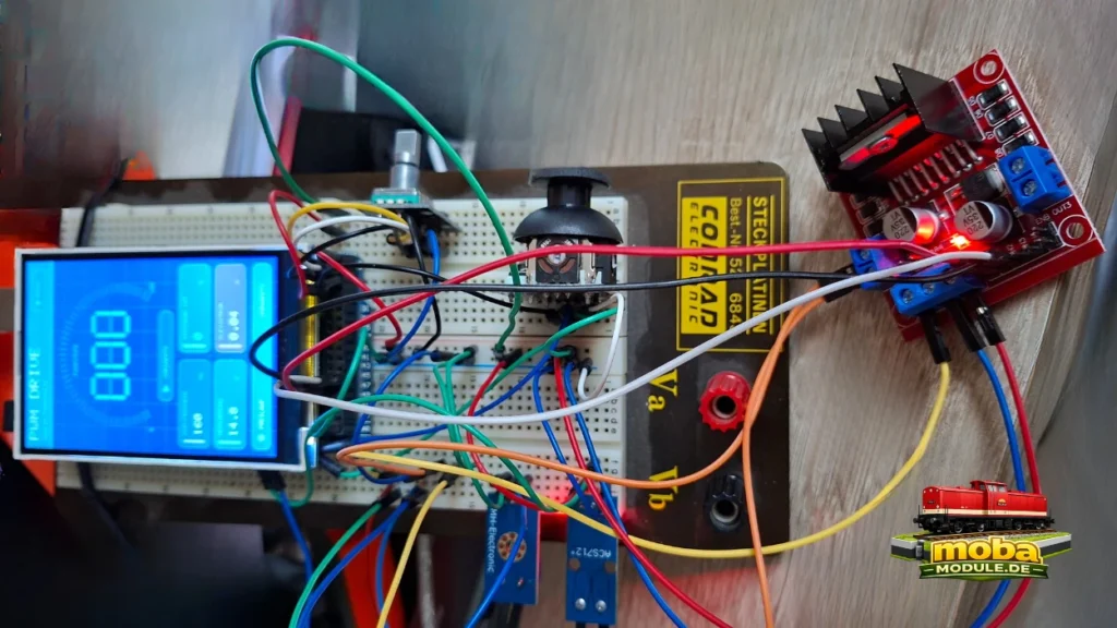
In Teil 3 dieser Serie habe ich den Systemaufbau des PWM-Fahrreglers beschrieben. Teil 4 zeigt nun, wie daraus der erste reale Versuchsaufbau entstanden ist. Es geht nicht um eine idealisierte Musterverdrahtung, sondern um den tatsächlich vorhandenen Prototyp mit Arduino Mega 2560, direkt aufgestecktem TFT-Shield, Bedienelementen, L298N-Leistungsstufe und den beiden Messmodulen.
Der Aufbau dient dazu, Bedienung, PWM-Ausgabe, Fahrtrichtungsumschaltung, Strommessung und Spannungsmessung gemeinsam zu erproben. Er ist damit ein Arbeitsstand zwischen Konzept und späterer dauerhafter Hardware. Die Grundlagen zur PWM und zur H-Brücke stehen in Teil 2; die Motivation und der Projektstart sind in Teil 1 beschrieben. Eine Übersicht über die gesamte Serie bietet die Projektseite zum PWM-Analogfahrregler.
Die tatsächlich verwendeten Komponenten
Für den ersten Aufbau habe ich bewusst Bauteile verwendet, die bereits vorhanden, günstig erhältlich, bei vielen Händlern verfügbar und im Fehlerfall einfach austauschbar sind. Für einen Prototyp ist außerdem wichtig, dass sich eine Baugruppe schnell anschließen, prüfen und gegebenenfalls ersetzen lässt. Diese Auswahl macht den Aufbau auch für andere Modellbahner grundsätzlich nachbaubar.
„Günstig“ bedeutet dabei nicht automatisch „ungeeignet“ oder „unterdimensioniert“. Der reale Aufbau ist eine Erprobungsplattform. Erst Messungen und praktische Fahrtests zeigen, welche Komponenten ausreichend funktionieren und wo später eine technisch bessere Lösung sinnvoll wird. Insbesondere der L298N ist keine moderne Effizienzreferenz, für den ersten nachvollziehbaren Aufbau aber weit verbreitet und leicht zu beschaffen.
- Arduino Mega 2560
- direkt aufgestecktes 3,5-Zoll-TFT-Shield mit ILI9486-Controller
- KY-040-Drehgeber
- analoges Joystick-Modul mit VRx, VRy und SW
- rastender Stoppschalter mit NC- und COM-Kontakt
- L298N-Motortreibermodul
- ACS712-Stromsensormodul
- Spannungssensormodul für maximal 25 V
- Steckbrett beziehungsweise Entwicklungsplatine und Jumperkabel
- externe 15-V-Gleichspannungsversorgung
- angeschlossenes Gleis und eine analoge Modellbahnlokomotive für spätere Tests
Das TFT-Shield sitzt direkt auf dem Arduino Mega 2560
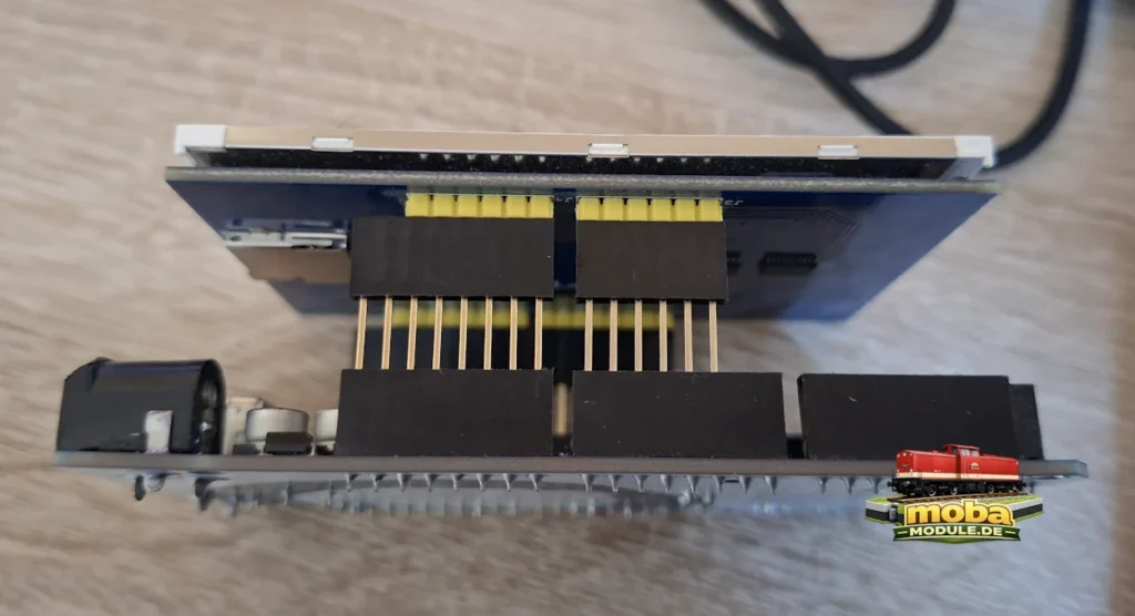
Das 3,5-Zoll-TFT ist in diesem Projekt kein separat über Jumperkabel angeschlossenes Display. Das Displaymodul ist ein Shield. Seine Stiftleisten sitzen direkt in den zugehörigen Buchsenleisten des Arduino Mega 2560. Mega und TFT liegen dadurch mechanisch parallel und weitgehend deckungsgleich übereinander.
Zwischen Mega und TFT befindet sich keine zusätzliche Steckplatine, aber es müssen zusätzliche Pin-Header eingebaut werden. Dadurch wird ein genügend großer Abstand zwischen dem Mega-Board und dem TFT-Shield hergestellt und die Pin-Stecker können ohne Probleme in die anderen benötigten Pins eingesteckt werden. Es gibt auch keine lose Parallelverdrahtung zwischen beiden Baugruppen. Das Shield belegt zahlreiche Anschlüsse des Mega. Die zusätzlichen Baugruppen werden deshalb gezielt an noch verfügbaren Pins angeschlossen. Die weiter unten aufgeführte Anschlussliste ist die bestätigte Belegung dieses Prototyps.
Drehgeber, Joystick und Stoppschalter
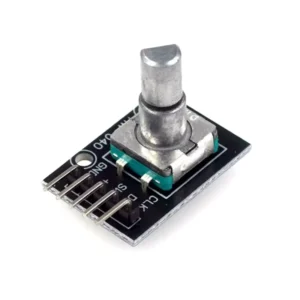
Der KY-040-Drehgeber ist mit CLK an D22, DT an D23 und SW an D24 angeschlossen. Die Drehbewegung dient zur Einstellung der Fahrstufen; der Tastendruck erhält eine definierte Bedienfunktion. Da die mechanischen Kontakte eines Drehgebers prellen können, muss die Software die Signale entprellen und Zustandswechsel eindeutig auswerten.
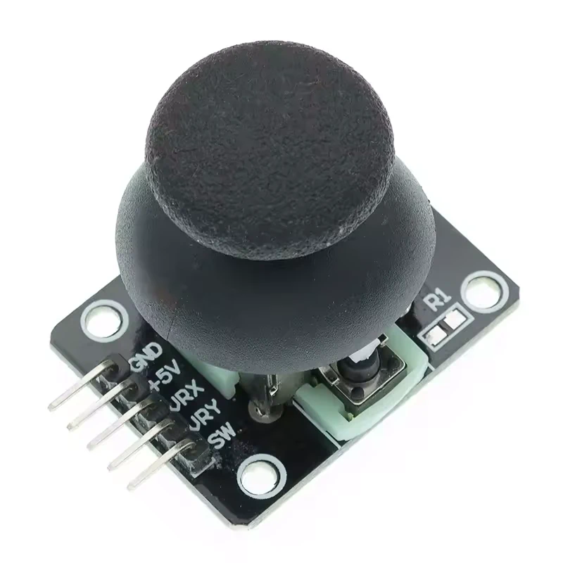
Beim analogen Joystick liegt VRx an A14, VRy an A15 und der integrierte Taster SW an D25. Die beiden analogen Achsen sind für Navigation beziehungsweise Auswahl vorgesehen, der Taster für eine Bestätigung. Mittelstellung und Randwerte werden nicht als ideale Festwerte angenommen. Sie müssen am realen Modul eingelesen und bei Bedarf kalibriert werden, weil Bauteiltoleranzen und mechanische Abweichungen den Wertebereich beeinflussen.
Der rastende Stoppschalter arbeitet im Öffnerprinzip: NC liegt an D26, COM an GND. Im normalen Zustand ist der Kontakt geschlossen. Bei Betätigung öffnet er den Stromkreis am Eingang. Der Eingang soll mit einer definierten Pull-up-Logik betrieben und von der Software eindeutig ausgewertet werden.
Im vorhandenen Prototyp wird dieser Kontakt vom Mega ausgewertet. Daraus folgt ausdrücklich keine vollständig unabhängige hardwareseitige Trennung der gesamten 15-V-Einspeisung.
Motorsteuerung über das L298N-Modul
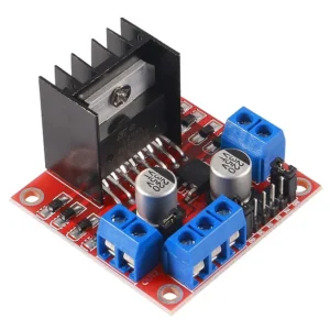
Die Motorsteuerung übernimmt ein L298N-Modul. D46 ist mit ENA verbunden und trägt das PWM-Signal. D44 steuert IN1, D45 steuert IN2. Über IN1 und IN2 wird die Polarität am verwendeten Ausgangskanal und damit die Fahrtrichtung bestimmt. OUT1 und OUT2 bilden den Ausgang zum Gleisstrompfad.
Der Arduino Mega darf den Motor- beziehungsweise Gleisstrom nicht direkt liefern. Er erzeugt nur die Steuersignale. Die eigentliche Leistung wird vom L298N geschaltet. Das Modul ist günstig, weit verbreitet und einfach erhältlich, besitzt aber relevante Spannungsabfälle und Verlustleistung. Es ist weder eine moderne noch eine besonders effiziente Ideallösung. Sein thermisches Verhalten muss im realen Betrieb beobachtet werden.
Fahrtrichtungswechsel dürfen nicht bei hoher Fahrstufe oder hohem Motorstrom erfolgen. Vor einer Richtungsumkehr muss die Software kontrolliert auf Fahrstufe null abbremsen, den Ausgang in einen sicheren Zustand bringen und erst danach die Polarität ändern. Diese Reihenfolge schützt zwar nicht pauschal vor jedem Fehler, vermeidet aber eine unnötig harte elektrische und mechanische Umschaltung.
Strom- und Spannungsmessung
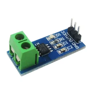
Das ACS712-Modul wird mit 5 V versorgt, liegt mit GND an der gemeinsamen Masse und gibt sein analoges Sensorsignal an A8 aus. Der Laststrom wird nicht über den Analoganschluss gemessen, sondern durch die beiden Schraubklemmen des Moduls geführt. Deshalb liegt das Modul in Reihe im Gleisstrompfad.
Das Ausgangssignal des ACS712 ist ein analoger Messwert. Nullpunkt, Empfindlichkeit, Rauschen und Abweichungen müssen am realen Aufbau kalibriert werden. Die Stromrichtung beeinflusst das Vorzeichen der Messabweichung beziehungsweise die Richtung des Messsignals. Deshalb ist die Orientierung von Klemme 1 zu Klemme 2 fest dokumentiert: OUT2 des L298N führt zu Klemme 1, Klemme 2 führt zu Gleis 2.
Das Spannungssensormodul liegt mit S an A9 und mit Minus an der gemeinsamen Masse. An der Schraubklemme liegt Plus an Netzteil +15 V und Minus an Netzteil GND. Damit misst das Modul die Versorgungsspannung des Leistungszweigs. Der Analogwert muss mit einem realen Multimeter abgeglichen werden. Das übliche 0-bis-25-V-Modul ist ein passiver Spannungsteiler und keine galvanische Trennung.
Für beide Sensoren werden an dieser Stelle bewusst keine erfundenen Kalibrierwerte oder Messgenauigkeiten genannt. Erst die Messung am konkreten Modul und im konkreten Aufbau liefert verwertbare Korrekturfaktoren.
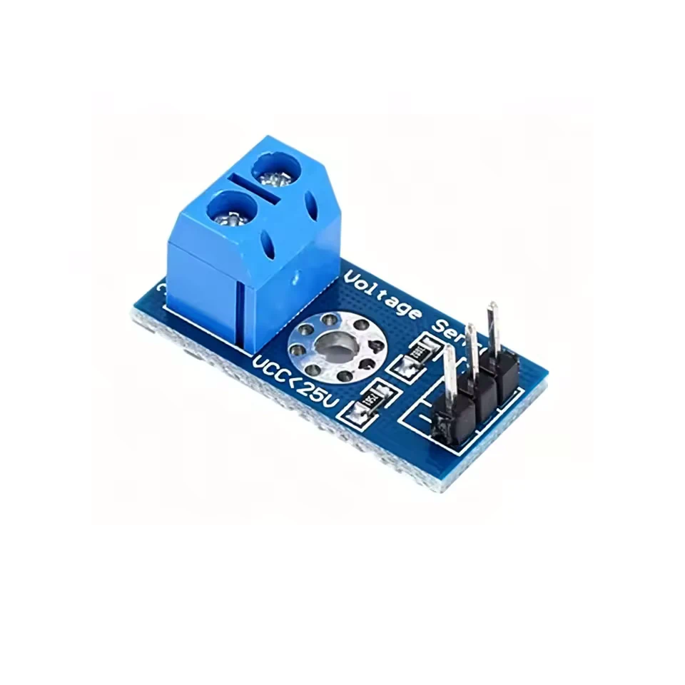
Versorgung, gemeinsame Masse und Leistungsstromkreis
Im Aufbau müssen vier Dinge sauber unterschieden werden: die 5-V-Logikversorgung, die 15-V-Leistungsversorgung, die gemeinsame Masse als Bezugspotential und der Motor- beziehungsweise Gleisstrom. Die 5-V-Leitung versorgt die Logikanschlüsse des L298N sowie das ACS712. Die externe 15-V-Gleichspannungsversorgung speist den Leistungszweig des L298N und den Eingang des Spannungssensors.
ACHTUNG! 5-V-Jumper und ENA1-Jumper auf dem Shield abziehen!
Alle genannten Module benötigen im vorhandenen Aufbau ein gemeinsames Bezugspotential. Netzteil-GND, Mega-GND, L298N-GND, ACS712-GND und Spannungssensor-Minus sind miteinander verbunden. „Gemeinsame Masse“ bedeutet aber nicht, dass beliebige Leitungen ungeordnet zusammengesteckt werden können. Die Rückstromwege müssen nachvollziehbar bleiben, besonders dort, wo gepulster Motorstrom und empfindliche Analogmessung zusammenkommen.
Leistungsstromleitungen sollen möglichst kurz und ausreichend dimensioniert sein. Messleitungen sollten nicht unnötig parallel zu stark gepulsten Leitungen geführt werden. Jumperkabel und Steckbrett sind für den ersten Versuchsaufbau praktisch, aber keine endgültige Dauerlösung für den Gleisstrom. Der Motorstrom fließt über den L298N-Ausgang, das Gleis, die Lok und auf der zweiten Schiene über den ACS712 zurück zum Ausgangskanal.
Der vollständige Gleisstrompfad
Der Stromweg lässt sich in acht Schritten nachvollziehen: Das Netzteil versorgt den L298N über +15 V und GND. Der L298N schaltet diese Versorgung über OUT1 und OUT2. OUT1 führt unmittelbar zu Gleis 1. OUT2 führt zunächst zu Klemme 1 des ACS712. Der Strom durchläuft den ACS712 und verlässt ihn über Klemme 2. Von dort führt die Leitung zu Gleis 2. Damit liegt der ACS712 in Reihe im Gleisstrompfad. Der Motorstrom der Lok fließt durch den Sensor und kann als analoges Signal über A8 ausgewertet werden.
Netzteil +15 V ─────────────── L298N +12V/VS
Netzteil GND  ──────────────── L298N GND

L298N OUT1 ─────────────────── Gleis 1
                                  │
                              Lokmotor
                                  │
L298N OUT2 ── ACS712 Klemme 1 ── ACS712 ── Klemme 2 ── Gleis 2

ACS712 OUT ─────────────────── A8 am Arduino Mega 2560
Das Diagramm bildet nur die einfachen Verbindungen ab. Es ergänzt keine Schutzschaltung, keine zusätzliche Sicherung und keine weitere Verdrahtung.
Anschlussliste des Prototyps
| Bereich | Mega beziehungsweise Versorgung | angeschlossene Baugruppe | Anschluss | Funktion |
|---|---|---|---|---|
| Bedienung | D22 | KY-040 | CLK | Drehimpulse für die Fahrstufeneinstellung |
| Bedienung | D23 | KY-040 | DT | Richtung der Drehbewegung |
| Bedienung | D24 | KY-040 | SW | Tastendruck des Drehgebers |
| Bedienung | A14 | Joystick | VRx | analoge X-Achse |
| Bedienung | A15 | Joystick | VRy | analoge Y-Achse |
| Bedienung | D25 | Joystick | SW | integrierter Bestätigungstaster |
| Bedienung | D26 | Stoppschalter | NC | Öffner-Eingang für die Stoppfunktion |
| Bedienung | GND | Stoppschalter | COM | Bezug für den Öffnerkontakt |
| Motorsteuerung | D46 | L298N | ENA | PWM-Signal für den Ausgangskanal |
| Motorsteuerung | D44 | L298N | IN1 | Polarität beziehungsweise Fahrtrichtung |
| Motorsteuerung | D45 | L298N | IN2 | Polarität beziehungsweise Fahrtrichtung |
| Sensoren | A8 | ACS712 | OUT | analoger Strommesswert |
| Sensoren | A9 | Spannungssensor | S | analoger Spannungsmesswert |
| Versorgung und Logik | 5 V | L298N | +5V | externe Logikversorgung; Jumperzustand vor Freigabe prüfen |
| Versorgung und Logik | 5 V | ACS712 | VCC | Sensorversorgung |
| Versorgung und Logik | GND | L298N | GND | gemeinsames Bezugspotential |
| Versorgung und Logik | GND | ACS712 | GND | gemeinsames Bezugspotential |
| Versorgung und Logik | GND | Spannungssensor | − | gemeinsames Bezugspotential |
| Versorgung und Logik | GND | alle Module | gemeinsame Masse | gemeinsames Bezugspotential des Aufbaus |
| 15-V-Leistung | Netzteil +15 V | L298N | +12V/VS | Leistungsversorgung des Motortreibers |
| 15-V-Leistung | Netzteil +15 V | Spannungssensor | Schraubklemme + | Messung der Leistungsversorgung |
| 15-V-Leistung | Netzteil GND | L298N | GND | Rückleitung der Leistungsversorgung |
| 15-V-Leistung | Netzteil GND | Arduino Mega 2560 | GND | gemeinsames Bezugspotential |
| 15-V-Leistung | Netzteil GND | ACS712 | GND | gemeinsames Bezugspotential |
| 15-V-Leistung | Netzteil GND | Spannungssensor | Schraubklemme − | Bezug der Spannungsmessung |
| Gleisstrom | L298N OUT1 | Gleis | Gleis 1 | erste Leitung des Ausgangskanals |
| Gleisstrom | L298N OUT2 | ACS712 | Klemme 1 | Eingang des in Reihe liegenden Stromsensors |
| Gleisstrom | ACS712 Klemme 2 | Gleis | Gleis 2 | zweite Leitung nach dem Stromsensor |
Kontrolle vor dem ersten Einschalten
- Netzteil ausgeschaltet und spannungsfrei
- keine Verbindung zwischen +15 V und 5 V
- keine direkte Verbindung zwischen +15 V und Mega-Eingängen
- gemeinsame Masse kontrolliert
- Polarität des Netzteils kontrolliert
- L298N-Reglerjumper beziehungsweise 5V-EN am realen Board geprüft
- L298N ENA, IN1 und IN2 korrekt zugeordnet
- OUT1 und OUT2 nicht kurzgeschlossen
- ACS712 tatsächlich in Reihe und nicht parallel angeschlossen
- ACS712-Versorgung und Analogausgang geprüft
- Spannungssensor-Eingang und Ausgang nicht verwechselt
- Stoppschalter-NC und COM geprüft
- keine Lok auf dem Gleis während der ersten Logikprüfung
Alle Prüfungen erfolgen im spannungslosen Zustand. An der eingeschalteten Verdrahtung werden keine Leitungen umgesteckt und keine kurzschlussgefährlichen Prüfungen durchgeführt.
Grenzen des provisorischen Aufbaus
Der Steckbrettaufbau ist für Entwicklung und Tests gedacht. Lange Jumperkabel erhöhen Übergangswiderstände und Störeinflüsse. Steckkontakte können sich lösen, und ein übliches Steckbrett ist nicht für beliebig hohe Dauerströme geeignet. Gerade der gepulste Gleisstrom verlangt eine kritischere Betrachtung als reine Logiksignale.
Auch die Masseführung ist noch nicht optimal. PWM-Störungen können Messwerte beeinflussen, wenn Leistungs- und Signalleitungen ungünstig nebeneinander liegen oder Rückströme über gemeinsame dünne Verbindungen fließen. Mechanische Befestigung und Zugentlastung fehlen ebenfalls. Zusätzlich erzeugt der L298N relevante Verlustleistung, die im Versuch beobachtet werden muss.
Für einen späteren Dauerbetrieb ist deshalb eine sauberere Verdrahtung beziehungsweise eine eigene Platine sinnvoll. Der aktuelle Aufbau dokumentiert den realen Schritt, mit dem die bisher getrennt betrachteten Baugruppen erstmals als Gesamtsystem geprüft werden.
Wie es im nächsten Teil weitergeht
Der nächste Teil wird die praktischen Beobachtungen und Messungen am aufgebauten System behandeln. Dazu gehören die Reaktion der Bedienelemente, die Plausibilität von Strom- und Spannungswerten, das Verhalten der PWM-Ausgabe und die thermische Beobachtung der Leistungsstufe.
English version
From the system concept to the real test setup
In Part 3 of this series, I described the system architecture of the PWM throttle. Part 4 now shows how the first real test setup was built from that concept. This is not an idealized reference wiring diagram. It documents the actual prototype with an Arduino Mega 2560, a directly plugged-on TFT shield, control elements, an L298N power stage, and the two measurement modules.
The setup is intended to test the user controls, PWM output, direction switching, current measurement, and voltage measurement as one system. It is therefore a working stage between the concept and later permanent hardware. The PWM and H-bridge basics are explained in Part 2; the motivation and project start are described in Part 1. The PWM analog throttle project page provides an overview of the complete series.
The components actually used
For the first setup, I deliberately used parts that were already available, inexpensive to obtain, stocked by many suppliers, and easy to replace in the event of a fault. For a prototype, it is also important that a module can be connected, checked, and replaced quickly if necessary. This choice also makes the setup fundamentally reproducible for other model railroaders.
“Inexpensive” does not automatically mean “unsuitable” or “undersized.” The real setup is an experimental platform. Measurements and practical running tests will show which components work sufficiently well and where a technically better solution may later be worthwhile. The L298N in particular is not a modern benchmark for efficiency, but it is widely available and easy to source for a first traceable setup.
- Arduino Mega 2560
- directly plugged-on 3.5-inch TFT shield with ILI9486 controller
- KY-040 rotary encoder
- analog joystick module with VRx, VRy, and SW
- latching stop switch with NC and COM contacts
- L298N motor driver module
- ACS712 current sensor module
- voltage sensor module rated for a maximum of 25 V
- breadboard or development board and jumper wires
- external 15 V DC power supply
- connected track and an analog model locomotive for later tests
The TFT shield sits directly on the Arduino Mega 2560
The 3.5-inch TFT in this project is not a separate display connected with jumper wires. The display module is a shield. Its pin headers are inserted directly into the corresponding female headers of the Arduino Mega 2560. The Mega and TFT therefore lie mechanically parallel and largely aligned above one another.
There is no additional expansion board between the Mega and the TFT, but additional pin headers must be installed. This ensures sufficient spacing between the Mega board and the TFT shield, allowing the pin connectors to be plugged into the other required pins without any problems. There is also no loose parallel wiring between the two assemblies. The shield occupies numerous pins on the Mega. The additional assemblies are therefore connected specifically to the pins that are still available. The pinout list provided below is the confirmed pin assignment for this prototype.
The shield occupies numerous Mega pins. Additional modules are therefore connected specifically to pins that remain available. The connection list below is the confirmed pin assignment of this prototype; alternative pins from general Arduino examples are not part of this setup.
Rotary encoder, joystick, and stop switch
The KY-040 rotary encoder is connected with CLK to D22, DT to D23, and SW to D24. Rotation is used to set the speed steps, while pressing the encoder is assigned a defined control function. Because the mechanical contacts of a rotary encoder can bounce, the software must debounce the signals and evaluate state changes unambiguously.
On the analog joystick, VRx is connected to A14, VRy to A15, and the integrated push button SW to D25. The two analog axes are intended for navigation or selection, and the push button for confirmation. The center position and edge values are not treated as ideal fixed values. They must be read from the actual module and calibrated if necessary because component tolerances and mechanical deviations affect the range.
The latching stop switch uses the normally closed principle: NC is connected to D26 and COM to GND. In the normal state, the contact is closed; operating the switch opens the input circuit. The input is intended to use defined pull-up logic and must be evaluated unambiguously by the software. The stop switch is not an ordinary menu item. A broken wire should not go unnoticed as though it were a normal operating condition.
In the existing prototype, this contact is evaluated by the Mega. It therefore does not provide a fully independent hardware disconnection of the entire 15 V power circuit. Such an effect may only be claimed once an appropriate power disconnection has actually been implemented and verified.
Motor control with the L298N module
An L298N module handles motor control. D46 is connected to ENA and carries the PWM signal. D44 controls IN1, and D45 controls IN2. IN1 and IN2 determine the polarity on the channel in use and therefore the running direction. OUT1 and OUT2 form the output to the track current path.
The Arduino Mega must not supply the motor or track current directly. It only generates the control signals. The actual power is switched by the L298N. The module is inexpensive, widespread, and easy to obtain, but it has relevant voltage drops and power losses. It is neither a modern nor a particularly efficient ideal solution. Its thermal behavior must be observed under real operating conditions.
Direction changes must not be made at a high speed step or high motor current. Before reversing direction, the software must decelerate in a controlled manner to speed step zero, place the output in a safe state, and only then change the polarity. This sequence is not a blanket guarantee against every fault, but it avoids an unnecessarily harsh electrical and mechanical reversal.
Current and voltage measurement
The ACS712 module is supplied with 5 V, its GND is connected to the common ground, and its analog sensor output is connected to A8. The load current is not measured through the analog pin; it is routed through the two screw terminals of the module. The sensor is therefore installed in series in the track current path.
The ACS712 output is an analog measurement value. Zero point, sensitivity, noise, and deviations must be calibrated on the real setup. Current direction affects the sign of the measurement deviation or the direction of the measurement signal. The orientation from terminal 1 to terminal 2 is therefore fixed in the documentation: L298N OUT2 leads to terminal 1, and terminal 2 leads to track 2.
The voltage sensor module has S connected to A9 and its minus terminal connected to the common ground. At the screw terminal, plus is connected to the power supply +15 V and minus to power supply GND. The module therefore measures the supply voltage of the power branch. The analog value must be calibrated against a real multimeter. The common 0-to-25 V module is a passive voltage divider, not galvanic isolation.
No invented calibration values or measurement accuracies are given here for either sensor. Only measurements on the specific module in the specific setup can provide usable correction factors.
Supply, common ground, and power circuit
Four things must be clearly distinguished in this setup: the 5 V logic supply, the 15 V power supply, the common ground as a reference potential, and the motor or track current. The 5 V rail supplies the logic connection of the L298N and the ACS712. The external 15 V DC power supply feeds the L298N power branch and the input of the voltage sensor.
All listed modules require a common reference potential in the existing setup. Power supply GND, Mega GND, L298N GND, ACS712 GND, and voltage sensor minus are connected. However, “common ground” does not mean that arbitrary wires can be connected in an uncontrolled arrangement. Return-current paths must remain understandable, especially where pulsed motor current and sensitive analog measurement meet.
Power-current wiring should be as short as practical and adequately sized. Measurement wires should not run unnecessarily parallel to heavily pulsed power wires. Jumper wires and a breadboard are convenient for the first test setup, but they are not a permanent solution for track current. The motor current flows through the L298N output, the track, and the locomotive, and returns on the second rail through the ACS712 to the output channel.
The complete track current path
The current path can be followed in eight steps: The power supply feeds the L298N with +15 V and GND. The L298N switches this supply through OUT1 and OUT2. OUT1 leads directly to track 1. OUT2 first leads to terminal 1 of the ACS712. The current passes through the ACS712 and leaves through terminal 2. From there, the wire leads to track 2. The ACS712 is therefore in series in the track current path. The locomotive motor current flows through the sensor and can be evaluated as an analog signal at A8.
Power supply +15 V ────────── L298N +12V/VS
Power supply GND  ─────────── L298N GND

L298N OUT1 ────────────────── Track 1
                                  │
                           Locomotive motor
                                  │
L298N OUT2 ─ ACS712 terminal 1 ─ ACS712 ─ terminal 2 ─ Track 2

ACS712 OUT ────────────────── A8 on Arduino Mega 2560
The diagram shows only the confirmed connections. It does not add a protection circuit, an additional fuse, or any other wiring that is not explicitly documented in the real setup.
Prototype connection list
| Area | Mega or supply | connected module | terminal | function |
|---|---|---|---|---|
| Controls | D22 | KY-040 | CLK | rotation pulses for speed-step adjustment |
| Controls | D23 | KY-040 | DT | direction of rotation |
| Controls | D24 | KY-040 | SW | rotary-encoder push button |
| Controls | A14 | Joystick | VRx | analog X axis |
| Controls | A15 | Joystick | VRy | analog Y axis |
| Controls | D25 | Joystick | SW | integrated confirmation button |
| Controls | D26 | Stop switch | NC | normally closed input for the stop function |
| Controls | GND | Stop switch | COM | reference for the normally closed contact |
| Motor control | D46 | L298N | ENA | PWM signal for the output channel |
| Motor control | D44 | L298N | IN1 | polarity or running direction |
| Motor control | D45 | L298N | IN2 | polarity or running direction |
| Sensors | A8 | ACS712 | OUT | analog current reading |
| Sensors | A9 | Voltage sensor | S | analog voltage reading |
| Supply and logic | 5 V | L298N | +5V | external logic supply; verify jumper state before approval |
| Supply and logic | 5 V | ACS712 | VCC | sensor supply |
| Supply and logic | GND | L298N | GND | common reference potential |
| Supply and logic | GND | ACS712 | GND | common reference potential |
| Supply and logic | GND | Voltage sensor | − | common reference potential |
| Supply and logic | GND | all modules | common ground | common reference potential of the setup |
| 15 V power | Power supply +15 V | L298N | +12V/VS | power supply for the motor driver |
| 15 V power | Power supply +15 V | Voltage sensor | screw terminal + | measurement of the power supply |
| 15 V power | Power supply GND | L298N | GND | return of the power supply |
| 15 V power | Power supply GND | Arduino Mega 2560 | GND | common reference potential |
| 15 V power | Power supply GND | ACS712 | GND | common reference potential |
| 15 V power | Power supply GND | Voltage sensor | screw terminal − | reference for voltage measurement |
| Track current | L298N OUT1 | Track | Track 1 | first conductor of the output channel |
| Track current | L298N OUT2 | ACS712 | terminal 1 | input of the series-connected current sensor |
| Track current | ACS712 terminal 2 | Track | Track 2 | second conductor after the current sensor |
Checks before the first power-up
- power supply switched off and de-energized
- no connection between +15 V and 5 V
- no direct connection between +15 V and Mega inputs
- common ground checked
- power-supply polarity checked
- L298N regulator jumper or 5V-EN checked on the real board
- L298N ENA, IN1, and IN2 assigned correctly
- OUT1 and OUT2 not shorted
- ACS712 actually connected in series, not in parallel
- ACS712 supply and analog output checked
- voltage-sensor input and output not confused
- stop-switch NC and COM checked
- speed step at zero during startup
- track output disabled during startup
- no locomotive on the track during the first logic test
All checks are carried out with the wiring de-energized. Wires are not moved while the setup is powered, and no short-circuit-prone test methods are used.
Limits of the provisional setup
The breadboard setup is intended for development and testing. Long jumper wires increase contact resistance and susceptibility to interference. Plug connections can become loose, and a typical breadboard is not suitable for arbitrary continuous currents. Pulsed track current in particular requires more critical attention than logic signals alone.
The ground routing is not yet optimal either. PWM interference can affect measurements when power and signal wires run unfavorably next to each other or when return currents flow through shared thin connections. Mechanical mounting and strain relief are also absent. In addition, the L298N produces relevant power loss that must be observed during testing.
The current setup documents the real step in which the modules previously considered separately are tested together as a complete system for the first time.
What comes next
The next part will cover practical observations and measurements on the assembled system. These include the response of the control elements, the plausibility of current and voltage readings, the behavior of the PWM output, and thermal observation of the power stage.